The Import (DXF) dialog allows you to import a DXF (.dxf ) file that is exported from AutoCAD. DXF (drawing interchange format) files were created by Autodesk as a binary or ASCII representation of a drawing file. They can be used in eCADSTAR to add an image for a company logo, for example. The following versions of DXF file are supported.
- R12
- R13
- R14
- 2000
- 2004
- 2007
- 2010
- 2013
The imported file can be added to the displayed sheet in eCADSTAR Schematic Editor, or to the symbol that is open in Symbol Editor. In eCADSTAR Schematic Editor, this dialog also allows you to generate local symbols from blocks in the imported DXF file. Launch the Import (DXF) command by clicking Design > Import > DXF on the ribbon in eCADSTAR Schematic Editor or Symbol Editor. The settings that you enter in the dialog are saved as default values until eCADSTAR Schematic Editor or Symbol Editor is closed.
- Ellipses are converted to polylines when they are imported.
- You can specify the format of imported dotted lines or dashed lines by selecting a value in the Properties Panel, Line Type column.
- You cannot create a closed shape from a DXF file.
| Value | Description | |||||||||
|---|---|---|---|---|---|---|---|---|---|---|
| File | Allows you to enter the path to a valid DXF file. Alternatively,
click |
|||||||||
|
|
Allows you to select a file in the displayed Open dialog. The path to the DXF file is displayed in the File box. | |||||||||
| Scale | Allows you to specify the size of the imported image by entering
the factor by which its size is changed. Enter a numerical value
between 0.01 and 100.0.
|
|||||||||
| Translate block into symbol | In eCADSTAR Schematic Editor, this setting allows you to specify whether any blocks in the DXF file are converted to symbols or individual shapes. In AutoCAD, a block is a collection of objects that are combined into a single named object. | |||||||||
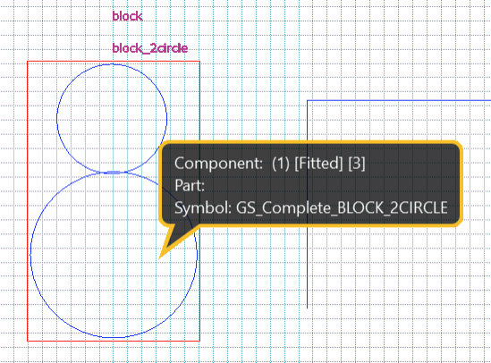
| Selected | Any blocks in the DXF data are added to the design as local
symbols, and are placed on the open sheet. If the Object
Balloon is toggled on, then the name of the symbol is displayed
when you point the cursor at it on the canvas. This is illustrated
below.
The block is automatically named using the name of the circuit diagram (.sct file). If the image is imported to a sheet, then the name of the design is used. If it is imported to a hierarchical block, then the name of the block is used.
For example, if the circuit diagram name is "sample.sct", then the names of imported blocks are converted as follows.
Note The following blocks are not converted to symbols.
|
|||||||||
| Not selected | Any blocks in the DXF file are expanded, and converted to individual figures. | |||||||||
| DXF file unit | Allows you to select the units that are used by eCADSTAR when displaying the imported image. | |||||||||
| mm | The imported image is displayed in units of millimeters. This is the default value. | |||||||||
| inch | The imported image is displayed in units of inches. | |||||||||
| Execute | Imports the specified DXF file to eCADSTAR Schematic Editor or Symbol Editor. The origin of the imported image is aligned with the origin of the sheet. This button is made available when you enter a value in the File box. | |||||||||
| Cancel | Closes the Import (DXF) dialog without importing a DXF file. |
When a DXF file is imported to eCADSTAR, the following types of ENTITY are converted.
- ARC
- ATTDEF
- ATTRIB
- CIRCLE
- ELLIPSE
- HATCH
- INSERT
- LINE
- LWPOLYLINE
- MTEXT
- POINT
- POLYLINE
- RAY
- SOLID
- SPLINE
- TEXT
- TRACE
- VERTEX
- XLINE
The following items are not converted.
- ENTITY types other than those listed above.
- Z coordinate values.
- External references to a block.
- The following functions for characters.
- Font shape
- Tilt
- Vertical writing
- Front-back inversion
- Up-down inversion.
- Line types of characters and patterns.


