
The eCADSTAR PCB Editor Interface
In this topic you will look at the eCADSTAR PCB Editor interface. The following window is displayed when a PCB design is opened. The functions shown in each box are explained below:
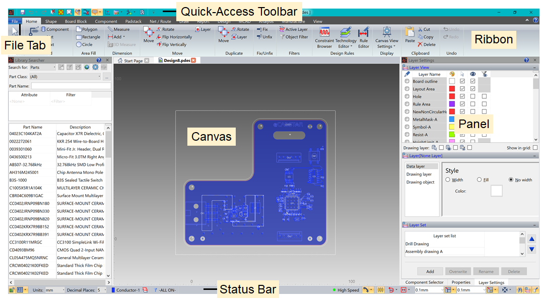
Figure 1: Exploring the eCADSTAR PCB Editor Interface
Each area shown in the above image is described in more detail below.
Features of the eCADSTAR PCB Editor interface
- Ribbon: contains the various categories from which options are selected. It is a layered element consisting of tabs, groups and controls.
- Canvas: displays the relevant PCB design.
- File Tab: allows you to execute operations on files, and provides general functions for application setting. These include the opening and closing of files, and saving and printing data.
- Quick Access Toolbar (QAT): allows you to select frequently-used commands. This toolbar can be customized to display the commands that you find most useful.
- Panels: the Layer Settings, Component Selector and Properties dialogs are provided as panels. You can drag and dock these panels, as required.
- Status Bar: contains the Message Log, Units, Active layer, Object filters and Cross Probe functions. DRC control, grids, snap and panel controls are also available. These allow you to quickly make changes to frequently-changed options.
3D View
On the View tab, click 3D View. The view mode will change, and a 3D compass will appear in the lower-right corner of the window. In this mode, strokes will still work, as well as the default keyboard pan X/Y and zoom functions. Clicking 3D View again will set the view back to 2D mode.
- To change the 3D view point use the 3D compass, shown in the bottom-right side of the screen.
- Dragging a handle changes the view point in the direction of the handle.
- Dragging a section other than the handles rotates the 3D compass in any direction.
As well as using the 3D compass, you can also select from seven preset views. You can use the Rotate operation, located in the 3D group, and then click directly in the window to change the view.
Application Settings
The Application Settings dialog is displayed by selecting File > Configuration > Application Settings on the eCADSTAR PCB Editor ribbon. This dialog contains numerous menus that allow you to define parameters. These include the following:
- Display settings
- Error Mark
- Canvas Information
- Save
- Interaction
- Area Fill Settings
- Technology
- Input Photo Data
- Hole Drawing
- Check Results
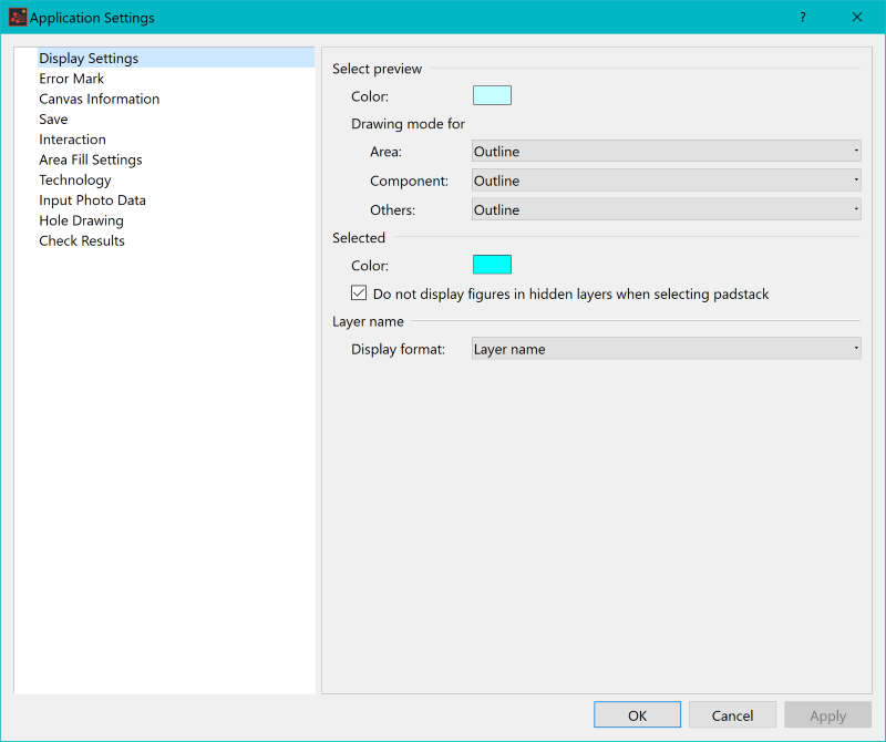
Figure 2: The Applications Settings Menu
Selection with the Mouse
Selection works in the same way throughout eCADSTAR.
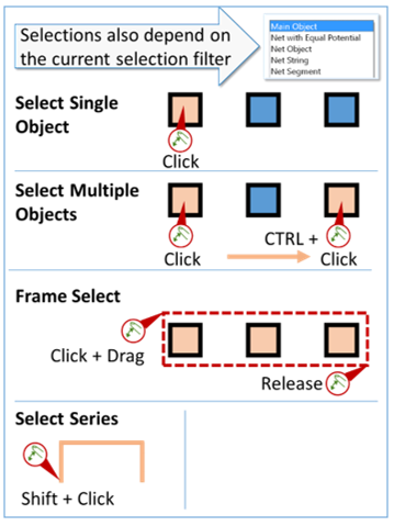
Figure 3: Selection with the Mouse
Stroke Commands
You can perform some viewing operations using the stroke commands shown below, so you do not have to move the cursor away from the canvas. To enter a stroke command, hold down the right mouse button and drag.
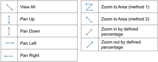
Figure 4: Stroke Commands
Tooltips
eCADSTAR provides Tooltip functionality. This is an additional feature, along with the standard ‘Help’ files, to assist you in using the application. Point the cursor at a field in a dialog to display the associated tooltip. For example, in the Add Text dialog, point the cursor at the Strings field, as shown below.
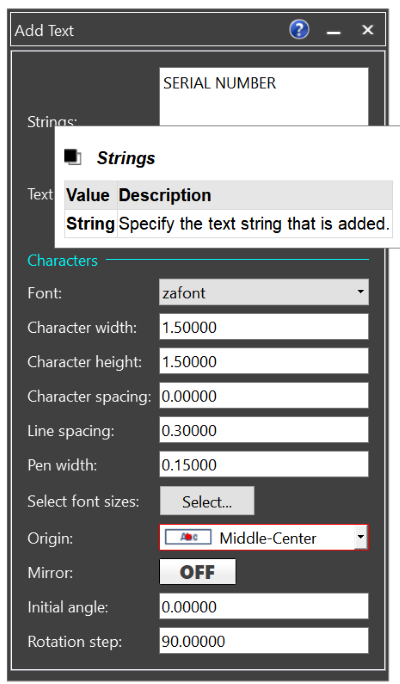
Figure 5: Tooltips
Operation manuals for eCADSTAR are provided as Online Help, rather than as printed media. To access these files:
- From the File tab, select Help.
- Select the current tool Help.
Current tool Help can also be accessed by pressing the F1 key, or by clicking the Help icon in a dialog or panel. This is illustrated below.
Figure 6: Help icons
You now understand the basic operation of eCADSTAR PCB Editor. You will create your own design in the next section.
Close any designs that are open in the eCADSTAR PCB Editor.
