

The Application Settings dialog allows you to specify the color of items that are previewed on the canvas, and set the position of property viewers. You can configure settings for rotating, copying, pasting and deleting objects on the canvas. Synchronization, Reference Designator and backup options can be specified, and DRC and Check Mode settings can be configured. It also allows you to configure SPICE Controller. Launch this dialog by clicking File > Configuration > Application Settings on the ribbon in eCADSTAR Schematic Editor or eCADSTAR Schematic Viewer.
Display Settings
| Value | Description | |
|---|---|---|
| Select Preview | Allows you to specify the color of items that are previewed on the canvas when the cursor is hovered over them. | |
| Color button | Displays the Select color dialog. Specify the preview color by selecting it in the dialog, and then clicking OK. When you hover the cursor over items on the canvas, they are displayed in the color that you specify. | |
| Selected | Allows you to specify the color of items that you select on the canvas. | |
| Color button | Displays the Select color dialog. Specify the color for selected items by clicking it in the dialog, and then clicking OK. Items that you select on the canvas are displayed in the specified color. | |
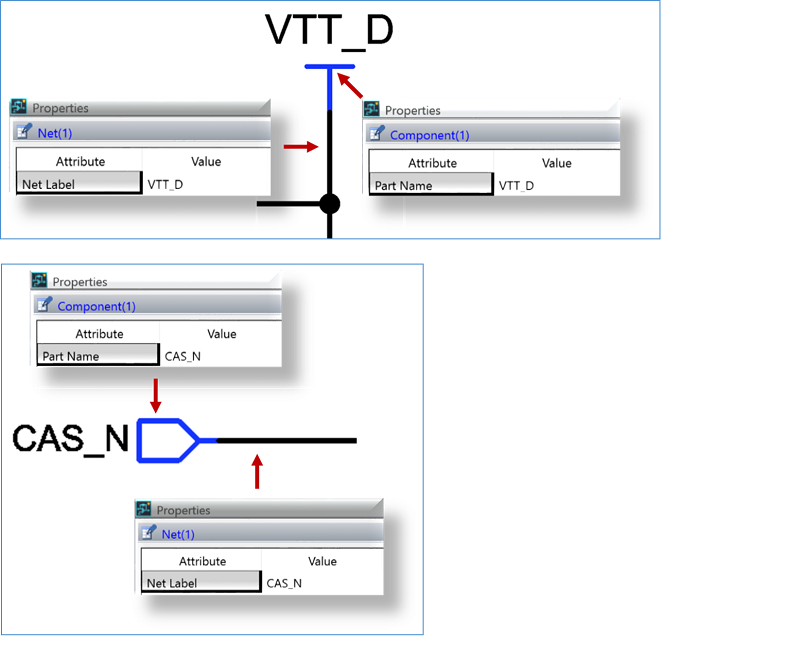
| Property viewer | Allows you to specify the position of Property Viewers that are displayed on the canvas. To display a Property Viewer, right-click the relevant row in the Properties Panel and select Display Viewer on the assist menu. | |
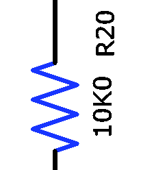
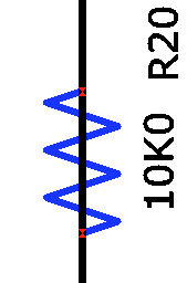
| Origin | Allows you to specify the origin of the property viewer by selecting an item in the Origin box. The origin is indicated by a red square. The position of the property viewer is defined in relation to its origin. | |
| Marks | Allows you to specify whether marks are displayed on the schematic sheets for unconnected pins and net nodes. These marks are helpful when creating a schematic sheet, but are not typically required after the schematic sheet has been created. | |
| Unconnected pins and Net nodes |
Note
You must close and then reopen the schematic sheet to apply the above changes. |
Advanced

A license is required to access the variation functionality in eCADSTAR.
Check
| Value | Description | |
|---|---|---|
| DRC | Allows you to specify whether components that are not fitted to the board are checked by the DRC command. | |
| Check not fitted components |
|
|
| Use E-Net for Matrix and Conflicting Pin Types checks |
|
|
| Check Mode | Allows you to identify overlapping nets, and nets that have the same value for Net Label, but are not connected. | |
| Net overlap check |
|
|
| Net label mismatch check |
|
SPICE Controller
LTspice Setting
| Value | Description | |||||||||||||||||||||||||||||||||
|---|---|---|---|---|---|---|---|---|---|---|---|---|---|---|---|---|---|---|---|---|---|---|---|---|---|---|---|---|---|---|---|---|---|---|
| Executable path | Displays the path to the LTspice executable file that you specify.
Click Note Before you execute a simulation, specify this path and then restart eCADSTAR. |
|||||||||||||||||||||||||||||||||
|
|
Select the LTspice executable file (*.exe) in the displayed Select executable path dialog. | |||||||||||||||||||||||||||||||||
| Command-line arguments | Specify the command-line arguments that are passed to the simulator.
Note
The following command-line arguments are supported.
It is recommended that -ascii is specified. This converts the data for the Operating Point Display into ASCII format. This enables it to be back annotated from the LTspice application into eCADSTAR Schematic Editor.
|
|||||||||||||||||||||||||||||||||
| Include file | Allows you to add and delete library files, and order them in the Include file table. These are text files that may comprise analysis statements, circuit nets or device models. In the SPICE Controller Manager, add them to the Analysis tree by clicking Insert Analysis Conditions, and then selecting Include files in the Analysis Conditions dialogs. These files are listed in the displayed Select an Include file dialog. If specified, then they are added when the simulation is performed. | |||||||||||||||||||||||||||||||||
| Include file table | Displays the library files that you specify using the
Add and Browse
buttons. Use the |
|||||||||||||||||||||||||||||||||
| Add | Adds a blank include file to the Include file table, in an editable state. Specify the path to an include file, and press Return. The path is shown in the table. | |||||||||||||||||||||||||||||||||
| Browse | Allows you to browse to an include file in the displayed Select include file dialog. The path to the selected file is shown in the table. | |||||||||||||||||||||||||||||||||
| Delete | Deletes the selected include file. You can delete multiple items using the Ctrl or Shift keys, or by dragging the cursor. | |||||||||||||||||||||||||||||||||
|
|
Moves the selected item up one row in the Include file table. You can select multiple items using the Ctrl or Shift keys, or by dragging the cursor. | |||||||||||||||||||||||||||||||||
|
|
Moves the selected item down one row in the Include file table. You can select multiple items using the Ctrl or Shift keys, or by dragging the cursor. | |||||||||||||||||||||||||||||||||
| Subcircuit | Allows you to add and delete subcircuit files, and order them in the Subcircuit table. This allows you to simulate part of a hierarchical design as a subcircuit. | |||||||||||||||||||||||||||||||||
| Subcircuit table | Displays the subcircuit files that you specify using the Add and Browse
buttons. Use the |
|||||||||||||||||||||||||||||||||
| Add | Adds a blank subcircuit file to the Subcircuit table, in an editable state. Specify the path to a subcircuit file, and press Return. The path is shown in the table. | |||||||||||||||||||||||||||||||||
| Browse | Allows you to browse to a subcircuit file in the displayed Select subcircuit dialog. The path to the selected file is shown in the table. | |||||||||||||||||||||||||||||||||
| Delete | Deletes the selected subcircuit file. You can delete multiple items using the Ctrl or Shift keys, or by dragging the cursor. | |||||||||||||||||||||||||||||||||
|
|
Moves the selected item up one row in the Subcircuit table. You can select multiple items using the Ctrl or Shift keys, or by dragging the cursor. | |||||||||||||||||||||||||||||||||
|
|
Moves the selected item down one row in the Subcircuit table. You can select multiple items using the Ctrl or Shift keys, or by dragging the cursor. |
| Value | Description |
|---|---|
| OK | Saves the settings in the Application Settings dialog, and closes the dialog. |
| Cancel | Closes the Application Settings dialog without saving your changes. |
| Apply | Saves the settings in the Application Settings dialog. The dialog remains open. |
