

The Move and Align 3D Model commands allow you to move a 3D model that is assigned to a footprint, and align its position to the footprint. 3D models cannot be selected on the canvas.
Moving a 3D Model using the Axis Tool
Aligning a 3D Model to a Footprint
The Alignment Axis Tool Operating Handles
Moving a 3D Model
Move a 3D model as follows:
- On the ribbon, click 3D
Model > 3D Model >
 Move. The Move 3D Model dialog
is displayed.
Move. The Move 3D Model dialog
is displayed. - In the Move 3D Model dialog, specify the destination and click Execute.
Target object
The only target object is 3D model.
Assist menu
The following menu items can be selected by right-clicking the mouse:.
Command dialog
For details about the command dialog that is displayed when the command is executed, see: Move 3D Model Dialog.
Moving a 3D Model using the Axis Tool
The axis tool allows you to move a 3D model on the canvas. It is displayed in the position of the reference point that is specified on the 3D model, as shown below.
| Item | Description | |
|---|---|---|
| Axis handle | The arrow indicating the axis direction is called the "axis
handle". Drag along the axis handle to move the 3D model
along the associated axis on the canvas.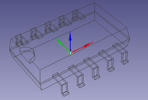 |
|
| Rotating handle | The circle located vertically in relation to each axis is called
the "rotating handle".Drag the rotating handle to rotate
the 3D model on the canvas.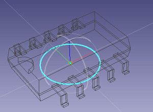 |
|
| Plane parallel move handle | The square between two axis handles is called the "plane
parallel move handle".The sides and inside of the square
can be operated. Drag the plane parallel move handle to move the
3D model along the specified plane.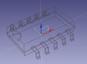 |
|
Aligning a 3D Model to a Footprint
Align a 3D model to a footprint as follows.
- On the ribbon, click 3D
Model > 3D Model >
 Align. The Align 3D Model dialog
is displayed.
Align. The Align 3D Model dialog
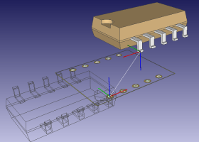
is displayed. - On the canvas, specify the reference point on the
footprint . The axis tool is displayed with its orientation fixed.
You cannot operate the axis tool on the footprint.
- On the 3D model on the canvas, specify the reference
point. A preview line is displayed that connects two axis tools.
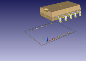
- Use the axis tool anchors to specify the orientation
of the 3D model in relation to the X-axis or Y-axis of the footprint.
A reference point is displayed on the 3D model. If necessary, reverse
the Z-axis direction of the axis tool by double-clicking it.
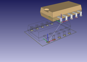
- Use the axis tool to adjust the position, and click Execute in the Align 3D Model dialog. The position of the 3D model is changed to the previewed position.
Target object
The only target object is 3D Model.
Assist menu
The following menu items can be selected by right-clicking the mouse:
Command dialog
For details about the command dialog that is displayed when the command is executed, see: Align 3D Model Dialog.
The Alignment Axis Tool Operating Handles
| Item | Description |
|---|---|
| X-axis handle | Represents the direction of the X axis. The end of this handle
is called the "X-axis anchor". Dragging the X-axis anchor
rotates the 3D model about the Z-axis handle. A circle representing
the XY plane appears when you are operating an anchor. You can
snap an anchor to the reference point of a 3D model. The anchor
snaps to the reference point when you release the mouse button
on the anchor.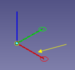 |
| Y-axis handle | Represents the direction of the Y axis. The end of this handle
is called the "Y-axis anchor". Dragging the Y-axis anchor rotates
the 3D model about the Z-axis handle. A circle representing the
XY plane appears when you are operating an anchor. You can snap
an anchor to the reference point of a 3D model. The anchor snaps
to the reference point when you release the mouse button on the
anchor.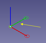 |
| Z-axis handle | Represents the direction of the Z axis. Double-clicking the
Z-axis handle reverses the direction of the axis tool.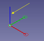 |
If the reference point that you attempt to snap an anchor to is not in the same plane as the X- or Y-axis handle, then the anchor snaps to where the reference point is projected onto the plane.
