

The Parametric Generation (Axial) dialog allows you to generate shapes for axial components. It is displayed by selecting Home > Generate >Parametric > Axial on the Footprint Editor ribbon. This command is only available in 2D View mode.
Pin Shape Tab
Symbol Mark Tab
Component Area Tab
Pin Shape Tab
Allows you to specify the configuration of the pins for an axial component, as shown below.
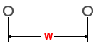
Pitch W
| Value | Description |
|---|---|
| Real number equal to, or greater than 0. | Specify the gap between pin shapes. |
Padstack Name
| Value | Description |
|---|---|
| String | Select the padstack that is used for the pin shape. |
Position
Specify the pin position that is set as the origin. Select from the following options:
- Center Pin
- Left Pin
- Right Pin
Symbol Mark Tab
Allows you to generate a symbol mark for an axial component.
Generate symbol mark
| Value | Description |
|---|---|
| Selected | Allows you to generate a symbol mark. All relevant fields in the Symbol Mark tab are made available. |
| Not selected | Specifies that a symbol mark shape is not generated. All fields in the Symbol Mark tab are made unavailable. |
Shape
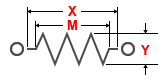
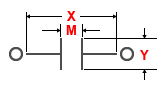
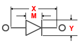
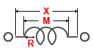
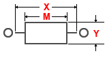
This setting is only made available if Generate symbol mark is selected. Specify a symbol mark shape from the following options. The dimensions shown on each image refer to the values in the Symbol mark shape settings table.
- Resistor
- Capacitor
- Diode
If selected, the Object section is made available.
- Inductor
- Rectangle
Symbol mark shape settings
The following settings are only made available if Generate symbol mark is selected.
| Parameter | Value | Description |
|---|---|---|
| Symbol length X | Real number greater than 0. | Specify the length of the symbol mark shape in the direction of the X-axis. |
| Symbol length Y | Real number greater than 0. | Specify the length of the symbol mark shape in the direction of the Y-axis. If the Shape field is set to anything other than Inductor, specify this value. |
| Mark width M | Real number greater than 0. | Specify the width of the symbol mark shape. |
| Mark radius R | Real number greater than 0. | Specify the radius of the symbol mark shape. If the Shape field is set to Inductor, specify this value. |
| Number of peaks | Integer equal to, or greater than 0. | Specify the number of peaks of the symbol mark shape. If the Shape field is set to Resistor or Inductor, specify this value. |
Object
The following settings are only made available if Generate symbol mark is selected.
Object
| Parameter | Description |
|---|---|
| Line only | A symbol mark shape is generated with only lines. Specify this value if the Shape field is set to Diode. If Lineonly is selected, the Pen width box is made unavailable. |
| Area fill and line | A symbol mark shape is generated with an area fill and a line. Specify this value if the Shape field is set to Diode. |
Line width
| Value | Description |
|---|---|
| Real number greater than 0. | Specify the width of the line. This field is only available when Line is selected. |
If the Shape field is set to anything other than Diode, a symbol mark shape is generated with lines alone.
Line attributes
The following setting is only made available if Generate symbol mark is selected.
Line type
Specify the format of the line.
| Value | Description |
|---|---|
| Solid | A solid line is generated. |
| Dash | A dash line is generated. |
| Dash dot | A dash-dot line is generated. |
| Dash dot dot | A dash-dot-dot line is generated. |
Area fill attributes
The following setting is only made available if Generate symbol mark is selected.
Pen Width
| Value | Description |
|---|---|
| Real number equal to or greater than 0. | Set the pen width of the area fill to be generated. |
Generation layer
The following setting is only made available if Generate symbol mark is selected.
| Value | Description |
|---|---|
| Layer name | Specify the layer on which a symbol mark shape is generated. |
Component Area Tab
Allows you to generate a component area for an axial component.
Generate component area
| Value | Description |
|---|---|
| Selected | Allows you to generate a component area. All fields in the Component Area tab are made available. |
| Not selected | Specifies that a component area is not generated. All fields in the Component Area tab are made unavailable. |
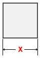
Length X
The following setting is only made available if Generate component area is selected.
| Value | Description |
|---|---|
| Real number greater than 0. | For a rectangular component area, this setting specifies the
X value of its dimensions. The default value is the same as Symbol length X on the Symbol
Mark tab.
|
Length Y
The following setting is only made available if Generate component area is selected.
| Value | Description |
|---|---|
| Real number greater than 0. | For a rectangular component area, this setting specifies the
Y value of its dimensions. The default value is the same as Symbol length Y on the Symbol
Mark tab.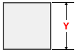 |
Height (Standoff - Maximum)
The following setting is only made available if Generate component area is selected.
| Value | Description |
|---|---|
| Real number equal to, or greater than 0. | Specify the spatial height of the component area. |
Generation layer
The following setting is only made available if Generate component area is selected.
| Value | Description |
|---|---|
| Layer name | Specify a layer from which to generate a component area. |
